Diffraction
What is diffraction?
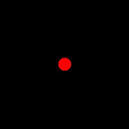
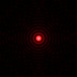
When starting out thinking about lasers, a lot of people think that the laser light just goes in a perfectly straight line forever. But no, physics is not as permissive as that. Light is a kind of wave, a wave made up of electric and magnetic fields but a wave nonetheless. And when waves encounter an obstacle, they can bend around the obstacle. Think of ripples in a still pond encountering a reed poking up through the water - the reed doesn’t cast a perfect shadow behind it. No, those ripples bend around and fill in the space behind the reed as well. In a similar way, if the ripples hit a wall with a hole in it, the ripples that go through the hole won’t march on in a perfectly straight column. Rather, they spread out as soon as they go through the hole. This bending and spreading out is called diffraction. Diffraction is a fundamental property of any wave in nature.[1]
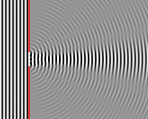
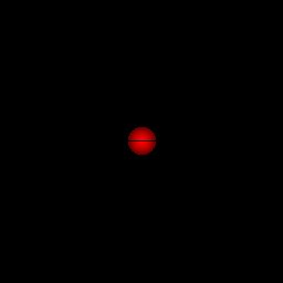
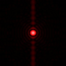
The smaller the wavelength of a wave in comparison to the size of the obstruction or opening, or the width of the beam, the less the wave diffracts. Since visible light has a very small wavelength, this is why light seems to travel in straight lines. It takes very narrow objects, such as hairs or thin scratches, or very long distances, to get noticeable diffraction. This is easy to demonstrate with a laser pointer in a darkened room. Shine the beam at a wall. Now put a hair in the beam. You will see a streak appear on the wall through the laser dot perpendicular to the hair. The streak is the light diffracting around the hair.
Spot Size
For a laser, we want to shine our beam on something. But as soon as the laser gets out of the machine that is making it and guiding it, it diffracts around the aperture that emits the beam into the wider world. This diffraction limits the amount by which the laser can be focused, or even by which it can move straight. This means that if you try to focus the beam down to a tiny point at a distant target, the beam might spread out to a much larger spot by the time it gets there. The amount the beam expands depends on the ratio of the initial width of the beam to the wavelength of the beam. In fact, we can determine the smallest possible spot size into which you can focus the beam: if we denote the diameter of the mirror, lens, or other opening in the laser or focusing element as D, the wavelength of the light as λ, and the distance to the target as R, then the diameter of the smallest spot, S, is given by[1]
This is called the Rayleigh critereon.
Note that to focus well, which gives you long range and maximizes your damage and armor penetration, you want to have your focal aperture be as large of diameter as you can get it! This is entirely the opposite of the intuitive idea that you want to shoot out a straight, narrow beam out of a small hole; because the beam is focused, not straight and wide apertures let you focus better. Just like a bigger diameter lens on your camera lets you take higher resolution pictures from a long way away, a bigger diameter lens or mirror on your laser gun lets your beam have a higher resolution (smaller spot size) when projected far away.
Diffraction also encourages using shorter wavelengths so you can focus damaging spots at longer ranges. Practically, you will probably not want to consider any wavelength longer than short-wave infrared for causing physical damage to a target. Historically, some long-wave and mid-wave infrared lasers were explored for laser weapons, but these are largely obsolete now. Microwave beams are used for counter-electronics weapons, but not for burning your target up because they simply can’t focus well enough. For space combat, you will want to use as short of a wavelength as is practically achievable by your technology. (In air, very short wavelengths have other problems.)
Beam Shape
A focused, diffraction limited beam can be approximated as converging on a focal point at range at R with a beam width
at any given distance x along the beam as long as W > S. Once W < S, the beam will propagate in a nearly collimated line for a distance
In practice, you will probably want to focus a distance Z/2 behind your target, in order to get the beam going straight for as long as possible once it encounters the target. When you take pictures, Z is called the depth of field, reflecting the limitations on the camera’s ability to focus at all distances. Likewise, we will refer to this distance for laser weapons as depth of focus for the same reason.[2] (Note that in the literature, the region where the beam is nearly parallel is the beam waist, our spot size S is closely related to the waist radius ω0 and our depth of focus is closely related to the Rayleigh range zR.)
Beam Quality
The equation given for the diffraction-limited spot size assumes that you have perfect beam quality. This means you need to be lasing in the best cavity modes of your laser. But sometimes other, unwanted modes creep in, and the more these modes contribute the worse your ability to focus becomes. These other modes diffract worse than the best modes. So good quality lasers end up being able to shoot much farther than poor quality lasers.
Often, lasers that are good quality at low power become worse quality as you try to shove more power through them. The extra power heats and distorts the laser generator, leading to lasing on multiple less favorable modes. Some lasers, such as free electron lasers and fiber lasers, are largely free of this issue. But other lasers like slab solid state lasers and especially diode lasers suffer from this.[3]
Interference and Phased Arrays
If you took an introductory class in physics during college, you might still remember the infamous double slit interference pattern[1]. If you have two apertures that remain in phase with each other (maybe a laser beam is being split in two and sent through both of them), and if the spots from the beams from both apertures overlap, then the beams will interfere with each other. For only two beams, you get a stripe pattern, but with multiple beams you can get more complicated patterns of spots.
Diffraction, it turns out, is just a special kind of interference. It is the pattern you get when you consider the waves of each different part of the aperture interfering with each other.
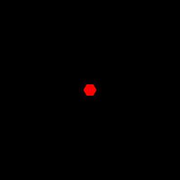
So here's an example of how we can use diffraction and interference to our benefit. here is a picture that shows a hexagonal aperture on the left and the diffraction pattern it produces at the target on the right (not to scale):
| 
|
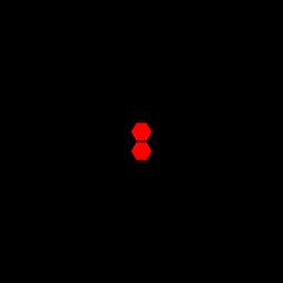
If we have two identical apertures and shine them at the same spot, we get some interference fringes. With the apertures nearly touching, as in this picture, the interference fringes are fairly broad. We get only one interference fringe in our illuminated spot and the illuminated area is essentially cut in half. We start getting hints of the neat things we can do when we note that if we shift the relative phases of the two apertures, we can control where the horizontal bar of the interference fringe occurs. In the picture below, the center image shows the interference pattern with no phase shift and the right-most picture how the fringe shifts if the relative phase between the two apertures is adjusted to about π/2 radians.
| 
| 
|
Phase control can be done electronically, so if you had paired apertures like in the above picture, you could rapidly scan the horizontal bar of the interference fringe up and down across the spot without moving any mechanical component.
But let's do better than that.
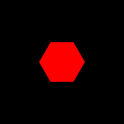
We know that a bigger aperture will produce a smaller spot
| 
|
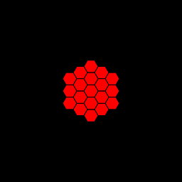
So lets try to approximate the single large aperture by tiling a while bunch of our small apertures together (left picture in the images below)
| 
| 
|
With no relative phase shift, we see that we can do almost as well as a single large aperture (middle). But if we introduce a relative phase shifts between our tiled apertures, we can move that spot around anywhere within the spot area of a single small aperture (right). We can now rapidly electronically scan a small spot over an area without having to mechanically move our beam pointer. This is called a phased array [4] .
We can now see the benefit of this method. If you have small individual apertures such that each has a fairly large diffraction spot, you can now rapidly flick your beam over that area. It might allow you to, for example, immediately switch between incoming missiles when you have blasted one and want to start blasting the next one without needing to cumbersomely move your giant beam pointer (and avoid all of the vibration and extra jitter that would entail). The smaller each individual aperture is, the larger the cone your beam can scan over. If you make each aperture smaller than the wavelength of the light it is emitting, your beam can be electronically steered over an entire hemisphere. While there are practical engineering issues to getting sub-micron apertures to remain in a sufficiently regular array with active phase control for each, perhaps this is something that can be done by a sufficiently advanced civilization. And even without sub-wavelength apertures, a tiled array of apertures with phase control would still have benefits even if the electronic beam steering is in a somewhat more restricted cone.
|
Do you like math? Nerd. But anyway, here's the math of what is really going on here. The shape of the diffraction spot amplitude is proportional to the 2-D Fourier transform of the aperture illumination amplitude profile. The intensity is proportional to the square of the amplitude's magnitude - converting to intensity gets rid to the phase information; the amplitude at each point is a complex number that can have different phases as you go across the aperture or the diffraction spot. If you have several copies of one aperture design moved to different places, mathematically this is a convolution of the aperture pattern with a series of points at the center of each of the apertures. You're familiar with the properties of a Fourier transform and the convolution theorem, right? Nerd. Okay, so the Fourier transform of a convolution is just the product of the Fourier transforms of the two functions in the convolution. In this case, it means we multiply together the diffraction spot of the individual aperture with the interference pattern you would get from the array of spots at the aperture centers. This is why you can't move the interference spot outside the single-aperture diffraction spot ... you are multiplying by that larger diffraction spot, and where the spot has zero value you can't get anything. |
Credit
Author: Luke Campbell
References
- ↑ 1.0 1.1 1.2 Douglas C. Giancoli, “Physics for Scientists and Engineers, Second Edition”, Prentice Hall, Englewood Cliffs, New Jersey (1988)
- ↑ Melles Griot. Gaussian Beam Optics
- ↑ RP Photonics Encyclopedia: Beam quality
- ↑ Kevin D. Bell, Michael K. Powers, Steven Griffin, and Steven Huybrechts, "Air Force Research Laboratory's Technology Programs Addressing Deployable Space Optical Systems", Part of the SPIE Conference on Space Telescoes and Instruments V, Kona, Hawaii, March 1998, SPIE Vol. 3356, 0277-786X1
